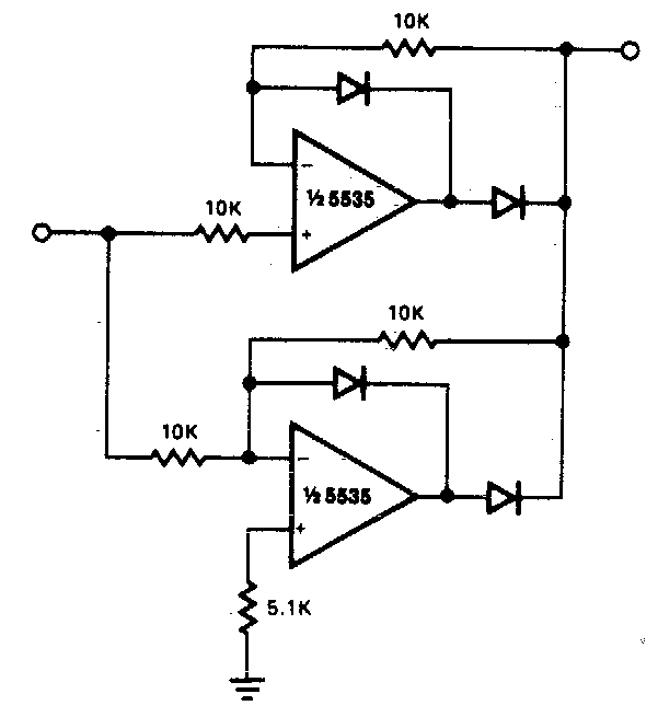
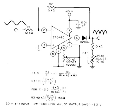
Full Wave Rectifier Diagram
Full wave rectifier circuit working and theory Rectifier wave half circuit diagram diode showing rectification ac operation crystal experiment supply connected used shown below pcb through What is full wave rectifier ?
Center Tapped Full Wave Rectifier - its Operation and Wave Diagram
Rectifier wave circuit capacitor theory working load do rl voltage calculate bridge diagram half output ac dc types its Circuit diagram of full wave rectifier with capacitor filter Build a full wave rectifier circuit diagram
Full-wave rectifier
Build a full wave rectifier circuit diagramFull wave bridge rectifier Rectifier studyFull wave rectifier : circuit diagram, types, working & its applications.
Precision full wave rectifier circuit diagramRectifier conventional rectifiers Rectifier transformer tapped output waveform inputHalf wave & full wave rectifier.

Rectifier wave tapped center circuit diagram operation its contents
Rectifier waveform inputRectifier wave Rectifier circuit diagramFull-wave rectifier.
What is half wave and full wave rectifier?Rectifier wave circuit theory bridge capacitor dc output ac voltage working load does rl input do work diagram calculate half Wave rectifier circuit diagram buildSchematic structure of the full-wave rectifier under study..

Wave rectifier circuit principle
Rectifier bridge waveform capacitor signal resistor dc circuitglobeWave rectifier circuit diagram build Rectifier wave circuit bridge voltage output working transformer tapped centre across load advantages consistsRectifier circuit diagram.
Rectifier wave circuit precision diagram simple ac dc circuitsstream sourced circuits gr nextRectifier center advantages disadvantages electronicscoach Center tapped full wave rectifierRectifier wave circuit tapped diagram center bridge diode capacitor theory filter diodes electronics transformer load engineering power fullwave tap also.

Full wave rectifier
.
.


